Or more like Parts 2a and 2b, since I have two short topics I want to discuss, related only by them both touching on the towers of the Clifton Suspension Bridge.
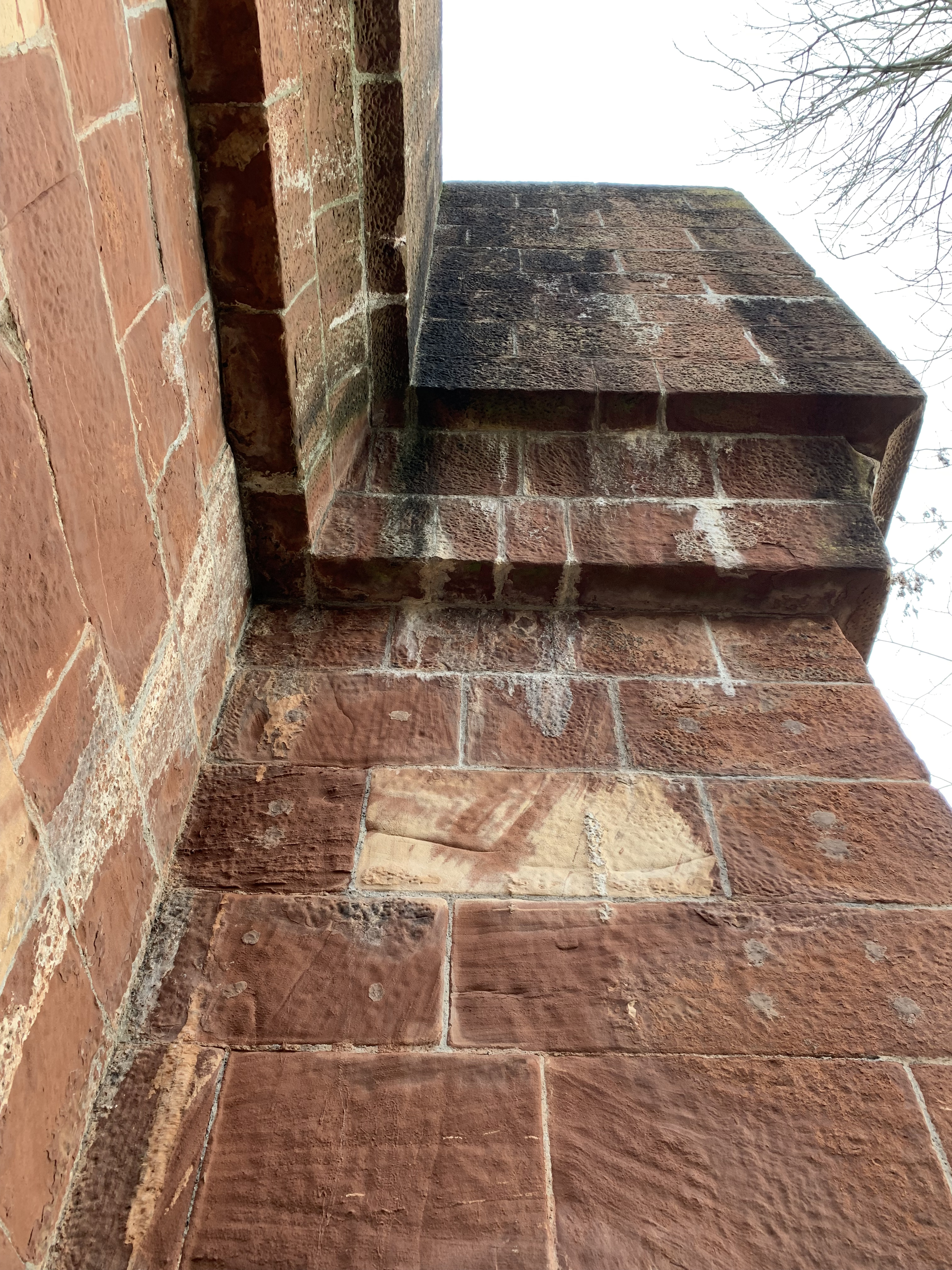
First, I remembered from the 1990s that the towers of the bridge are ashlar masonry, but I did not remember what kind. The picture above shows the west tower up close. The masonry is, officially, Pennant Sandstone, a carboniferous-era sedimentary rock found in Wales and western England. It appears to be a reasonably good building stone, as the 170+ years since the stone was placed seems to have not led to massive failures: no large face spalls, cracking, or disaggregation. The caved shapes in the picture look reasonably crisp. I’m mentioning this because the color and texture of the stone are quite close to the brownstone of the New York area (AKA Newark Triassic Sandstone) which is junk. I’ve seen a lot of brownstone used in much newer construction than the stone at Clifton fall apart from weathering. The moral of the story is quite deep: you can’t judge a book by its cover, not a stone by its color.
Second, the massive stone towers represent a view of suspension bridge analysis that is no longer current. This theory of analysis says that the towers are immobile, and therefore are gravity loaded only downward by the cables passing over the tower tops. (Also, the towers are loaded laterally by wind on themselves and on the road deck, but that’s not part of the topic at hand.) David Steinman, a man who knew his way around suspension bridges, illustrated it in 1922:

The towers and ground are hatched, which is a sketch shorthand for “immobile.” The accompanying text only discusses downward load from the cables on the towers. This is a reasonable accurate picture as long as the towers are much stiffer than the road deck and its trusses or girders. If the towers are much stiffer, then calculations for the remainder of the structure based on an assumption that the towers don’t move are okay. If you look at nineteenth-century suspension bridges, the towers are typically masonry or some form of metal trusses, and in both cases are quite stiff. The more modern and more complicated form of analysis assumes that the towers will bend in the plane of the cables depending on how the deck is loaded. This allows for much thinner steel and concrete towers, with one of the earliest large examples being the Manhattan Bridge. I’m not a big fan of the phrase “form follows function” when discussing architecture, but it makes a lot of sense in an engineering structure. The heavy masonry towers are meant to be immobile and their stiffness makes that assumption a reasonable one; the lighter deck and cables are known to move. The profile and the force diagram are nearly the same.
Part 1 is here. The finale will be tomorrow.


You must be logged in to post a comment.