I like to look at solutions that other engineers have used on problems similar to the ones I face. Not just engineers: builders and architects often suggest ideas that are worth thinking about. If I don’t like their solutions, I’m no worse off than I was before; if I like them then I can use the ideas. The bag of tricks that I use in design contains mostly clever ideas that other people thought of – sometimes 100 years ago, sometimes a few months ago – that are worth copying. I also try to remember where I get the ideas from: there’s a beam detail that I first saw suggested by a steel detailer and we’ve named it, internally, after him.
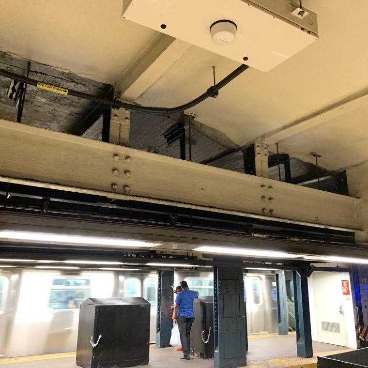
Old subway stations are great places to look at other people’s work, because the steel is exposed to view. The picture above shows a subway station that’s been altered. That’s quite common: every original station has been expanded, and a lot of the stations from the 1920s and 30s have been altered in some way. The basic structure of the old stations resembles a snake’s skeleton: a series of closely-spaced ribs that extend from the roof down the side. The concrete that fills the spaces between the steel beams that make up the ribs is reinforced, but a lot of it is acting as vaulting rather than slabs. So the vertical beams at the sides of the tunnel are carrying inward earth pressure, and the roof beams are carrying downward earth pressure and the weight of the roadbed above. The interior columns, one per beam, carry most of the vertical load of the beams down to the foundations. The typical spacing for each frame – a beam in the roof, interior columns between tracks and at the edges of platforms, and exterior columns at the outer walls of the tunnels and stations – is five feet on center.
In the station shown above, the BMT at Whitehall Street, two interior columns had to be removed at a platform for the (then new, now current) configuration. It’s easy enough to design a steel beam that can carry the column loads as a transfer girder, but how do you build that in situ, with some thirty feet of soil loading the station roof? The solution used here is that the transfer girder consists of a pair of channels, with the distance between the channels equal to the depth of the columns. The channels could be installed before the columns were removed, bolted into new holes drilled in the columns, and then the lower potion of the columns burned off below the channels. In the photo, the transfer girder is the beam right above the very bright lights. You can see the bolt heads at the two columns, the older riveted connections of the roof beams to the columns, and you can just make out the bottom of the columns behind the channel in front.

