I mentioned Bollman trusses once before, just about a year ago. They’re an obsolete form of structure, useful when there were few good analytic tools for trusses and when the connections of trusses were commonly made with eyebars, through-bolts, and pins. They were built in the 1850s and 60s, dying out in the early 1870s, and were typically used for railroad bridges. The Baltimore & Ohio Railroad in particular used this design a lot, so it’s fitting that the last one in service, spanning the Little Patuxent River at Savage, Maryland, was built by the B&O.
In a “pure” Bollman Truss, each cross-deck beam is supported by its own pair of wrought-iron tension rods, which carry the load back to cast iron towers at the ends of the span. The bridge above also has cross-bracing in each panel, which allows for some more-ordinary distribution of loads from one pair of tension rods to the next: the vertical above the deck beam ends is a cast-iron compression strut and its top will transmit force to the cross-bracing on either side, passing off some load to the neighboring pairs of tension rods. The amount of distribution can be calculated by comparing at the elongation (i.e., the stiffness) of the tension rods relative to the shortening of the struts and the elongation of the cross bracing (i.e., the stiffness) of the neighboring panels. That’s the kind of calculation that can rather annoying to perform by hand but is well suited to the graphic-statics methods popular in the nineteenth century starting around the same time Bollman trusses were dying out.
But that’s not my point…
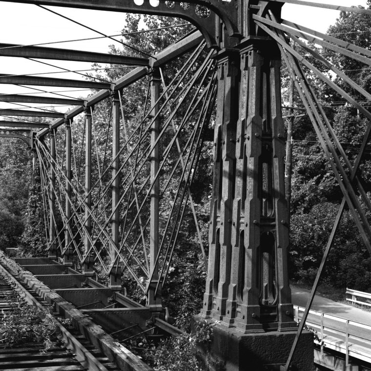
When these Bollman trusses were being built, most bridges in the US were made of wood. There were wood trusses, covered bridges where the trusses and arch-truss hybrids were hidden behind sheathing, and some wood girder bridges. There were some masonry arch bridges, but they were relatively rare. In that context, think of how alien this must have looked to most people:

A bunch of criss-crossed iron straps are going to hold up a moving train? No way.
Trusses in general show the logic that was used for their analysis: there can only be forces where there’s a piece of the truss, and the designers usually distinguish between tension members (thin and/or ductile metal) and compression members (thicker, heavier, and/or cast-iron). When I’m faced with an unrecognizable truss – usually a hybrid of some kind – I can immediately start tracing the force diagram just by looking at it. That’s not necessarily true of moment frames.
Most big buildings, prior to 1880 or so, relied on masonry or sheathed-timber walls for lateral stability. You can’t tell exactly how the wind forces are resolved just by looking and you often can’t even tell if an individual interior wall is engaged with the floor in a way that allows it to carry lateral load. Because the walls were bearing the floors, they were built at the same time and a construction view (either walking by at that time, or looking at a photo now) doesn’t necessarily tell you any more. The switch to skeleton framing meant that, during the brief time that the frame was visible during construction, you could see how a building’s loads were carried. In that context, Bradford Gilbert’s comment that the bracing of the Tower Building was “a bridge truss stood on end” was a clear effort to relate another scary new idea (tall, very slender buildings) to something that the general public was familiar with, even if they didn’t understand it.


Permalink