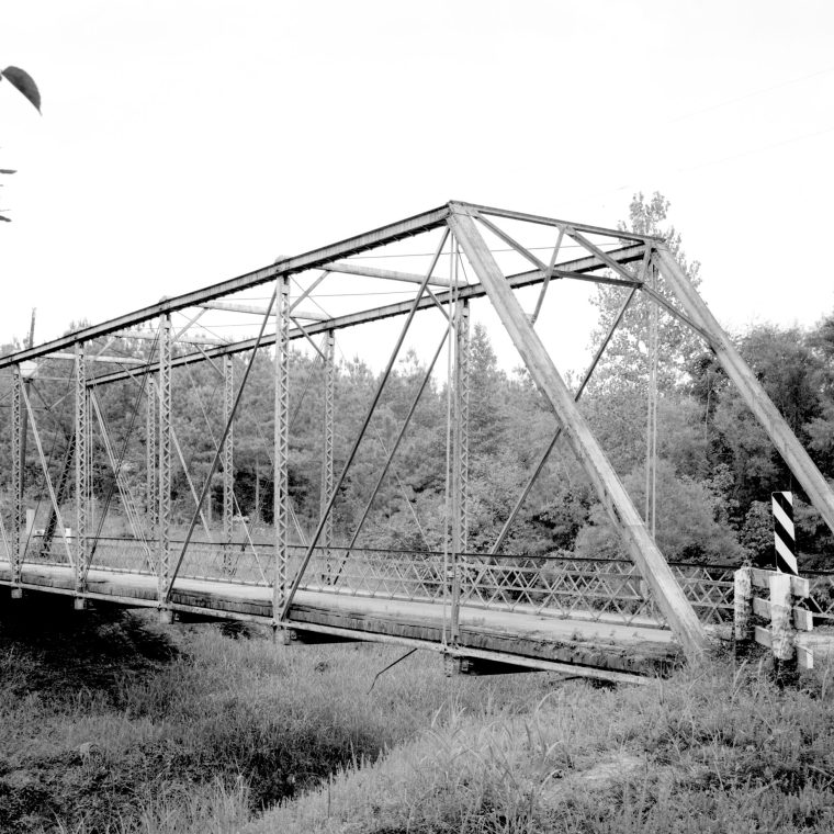
Yesterday’s post was, in my opinion, too theoretical to make my point, so I want to try going over the steps in an actual analysis of an actual structure. The bridge above is the 1912 “Edgefield County Bridge No. 3, Road S-63 spanning Log Creek, Pleasant Lane, Edgefield County, South Carolina.” It sounds nice and rural. Given that I’ve discussed a lot of truss bridges here, this seems like natural example, although it’s worth pointing out that I generally work on buildings and all of my truss analysis has been in buildings. The principles are the same, of course.
This is a single-span Pratt through-truss, constructed in an era when built-up members were still the norm. As a result, we get some insight on the designer’s intentions simply by the form of the members. More on that below…
At the highest level of abstraction, the entire bridge is a single-span beam, simply supported and uniformly loaded. In other words, my example from yesterday. The vertical-plane trusses on each side carry the gravity load, while the horizontal-plane trusses at the top and below the deck carry wind load. So, without getting too fancy, we can look at one of the vertical trusses in isolation as a beam carrying half of the overall gravity load. The governing formulas, as discussed yesterday, for demand are M=WL²/8 and R=WL/2, for moment and shear respectively. So far, so good: we’ve reduced this complex assembly of steel pieces to two equations from an intro to algebra class. Next up: what’s the capacity?
Steel beams tend towards H shapes because that shape is efficient in bending, assuming we assume that the bending moment is parallel to the central web (or around an axis perpendicular to the web, if you prefer). The metal is concentrated in the flanges, where it is best placed to resist the bending moment. The truss, as a beam, is not so obviously that shape, but with a little bit of imagination, you can see the top and bottom chords as the flanges of the H and the diagonals and verticals as the web. With a discontinuous shape like this, a good approximation of the bending strength comes from the formula I=Ad², where I is the overall moment of inertia, A is the cross-sectional area of the top and bottom chords (assumed to be equal for the moment), and d is the distance from the centroid of each chord to the mid-height of the truss. There are a lot of hidden assumptions here, but the big one is that the chords have the same area. The schematic capacity would then by Ma=(Fa)(I)/d, where Ma is the allowable moment and Fa is the allowable bending stress for the steel. (I’m simplifying a lot here, and also using the kind of steel design in use in 1912.)

Simple beam theory says that the bottom chord is in tension and the top is in compression. Tension is fairly easy with steel, and so the bottom chord consists of eyebars. You just have to make sure you account for the rivet (or in this case, pin) holes in your members. Compression is more problematic, as slender steel elements have a tendency to buckle. The top chord is a built-up box, made by riveting together two channels and two plates, to provide a shape more resistant to buckling than the flat bars of the bottom chord. Typically, the allowable stress in a slender compression member is also limited more than that in a tension member to help prevent buckling. But that’s getting us into tomorrow’s topic.
There isn’t as simple a way to convert the maximum shear – R in the equation above – to forces in the web members. This is where this extremely simple model stars to break down. Based, again, on beam theory, we know that the forces in the web members will be less than those in the top and bottom chords. But there’s really no way to address this without going to the next level of detail in analysis. The most abstract possible model got us an approximation of chord forces and therefore a preliminary size for the chords.
Tomorrow: 2D truss analysis.


You must be logged in to post a comment.