
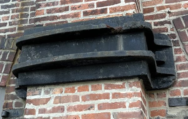
That complicated detail has a lot of steel to support a barely-usable balcony. Ever since steel framing in big buildings began in earnest – at the time of the publication of Architectural Terra Cotta, some 25 years earlier – people had used outrigger beams to support cornices, balconies and other projections. An outrigger – annoyingly called an “outlooker” in a lot of old texts – is simply a small cantilever beam shaped to provide support for masonry. Inverted Ts and inverted double angles are the most common forms of outrigger. The early forms of outrigger were simply embedded in thick brick walls, resolving the moment at the back end of the cantilever by bearing against the masonry above and below. This details shows something else: a framed system. Looking at the details on that page makes it clear. First, a transverse section of the balcony, parallel to the wall:

The typical outriggers are pairs of 2 inch by 4 inch angles, with the 4 inch legs vertical for greater strength and the 2 inch legs providing a seat for the terra cotta blocks of the balcony soffit. The outriggers also carry the concrete floor that has been cast using the terra cotta as a form. The end outrigger is slightly bigger and carries the bracket below through a hanger rod. Note that this is a reversal of classical masonry technique: the brackets, on the kind of solid ashlar balcony that this is imitating, are structural, helping to carry the floor above. Now the longitudinal section:
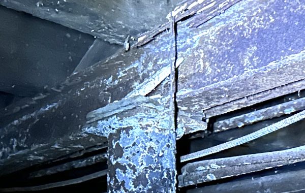
The outriggers are the dashed rectangle just below the words “damp proofing.” The cantilever moment creates maximum downward pressure on the outer face of the wall and maximum upward pressure at the back face of the wall. If you’re using steel outriggers to support a water table or cornice with several feet of masonry above, you can probably just embed the angles in the wall and be done with it. But here, with a balcony, there’s just about no wall above the outriggers and therefore nothing for the upward pressure to bear against. Instead, we have a steel angle, called out on the far left as 4 inches by 6 inches, and toed down to catch the upward force. Note that there’s also a steel bar near the front face of the wall to distribute the downward pressure over the masonry. This raises the question of what that angle in the back is actually doing. Note the dashed lines indicating the column beyond: the angle is aligned with the rear face of the column. Frankly, that angle only makes sense if it is attached somehow to the building frame.
So we’ve got a masonry and concrete balcony supported on outriggers, the outriggers bear down on the wall and up on a catchment angle, and the catchment angle spans between a pair of columns. That’s a lot of hopefully-not-moving parts, particularly for steel exposed to weathering because it’s in or outboard of the exterior wall.
You must be logged in to post a comment.