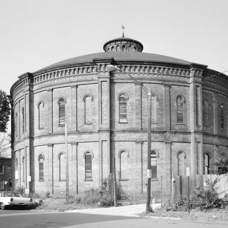
That odd round building in the photo above was the first time I encountered a structure that was a designed mix of wrought-iron and masonry. It’s the Gasholder House in Troy, New York. I was introduced to it when I was a student, not in an engineering class, but by a history professor, Tom Carroll. For some odd reason, the HAER survey for this building is not listed under “gasholder” in the HABS/HAER index.
The building itself is simple to describe, although a little odd because of the circular plan. The solid brick exterior wall supports the domed roof; the roof is framed with radial iron trusses.

Even though it’s not really the point of today’s post, the drawings that were included in the HAER documentation are simply too good to not show here. First, a plan of the roof trusses and elevations of the Warren main trusses and the tension-rod girder intermediate trusses:

And then a fantastic exploded view of the construction of the main trusses:

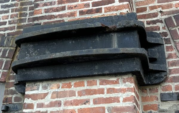
There’s an aspect of the design – it’s not really a problem, and there’s a rational reason for it so it’s not an oddity – that even drawings this good don’t quite make clear. There is no direct relationship between the main trusses and the brackets, rails, and pulleys that were mounted directly below the trusses’ wall-bearing ends. The reason those two elements – the roof trusses and the internal machinery – were spatially adjacent is that both required heavier support than the thin (12-inch) brick enclosure wall. In the photo at the top you can see the heavier piers that were built integrally with the wall. They are not buttresses in the ordinary sense, but rather columns, in masonry, strong enough to carry the weight of the roof (and the heavy snow loads of Troy) and to carry the dynamic loads on the rails. Which raises the question of what the rails are for…
The use of coal gas in the nineteenth century for lighting meant that there needed to be a way to store large amounts of gas locally, to be sent to the buildings where it was burned. And it had to be sent from the storage into the mains under roughly constant pressure so that the lamps didn’t flare up during a pressure spike or go out during a pressure drop. And, since the gas was flammable, potentially explosive, and can cause asphyxia if inhaled in more than small amounts, the storage had to be gas-tight. The solution was to use metal boxes, round in plan and upside down, so that the top is sealed and the bottom open. The box sat in a pit in the ground that was filled with water. Gas was stored in the box by pumping it in from below; as it collected under the box top it displaced water and the box would rise out of the pit. The water around the outside of the box acted as a seal to keep gas from escaping, sort of like the trap in a sink drain in reverse. The weight of the box kept the gas at the roughly constant pressure, so that as gas was sent out into the mains the box would drop back down. The rails seen in the drawings are to guide the box straight up and down so it didn’t jam against the outer wall; the pulleys were for counterweights to allow free movement and reduce the gas pressure.
The brick wall was not needed. Modern gasholders (for natural gas used for cooking and heating) use a metal skeleton frame around the boxes, and something similar could have been done here. But the brick wall with fake windows humanized this piece of new technology, making it look more like an ordinary building. “The gasholder house” sounds friendlier than “the gas tank.”

You must be logged in to post a comment.