
My latest look at the HABS/HAER index turned up “steel I-beams” as a category, and I obviously had no choice but to take a look. Most of the surveys with that tag were truss bridges. I’m interested in trusses, but I wanted something different. The photo above is from the HABS survey of the Raritan Arsenal. The location is listed as “near Bonhamtown” in New Jersey; as someone partially familiar with the area, I’d say that it’s nearer the town of South Edison. It’s a non-negligible train ride or drive southwest from midtown Manhattan, but it’s actually quite near Perth Amboy, which is near the extreme tip of Staten Island. In other words, this is not an urban area, but it’s closer to New York City than you might think.
This building was an expansion of the arsenal’s machine shop, constructed for World War II and used for repairs and modification of artillery. As of 1996, when the HABS survey took place, it was abandoned and scheduled for demolition, and I assume that took place. The reason I like this picture is it shows something I was taught in my first steel-design class (in either the fall of 1984 or the spring of 1985) and which I have not designed since: crane rail supports. This is a case where it’s definitely easier to show than to tell…
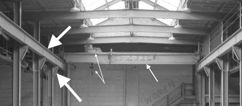
The skinny arrows point to a hook and a motor. The hook attaches objects to the crane, which can be raised or lowered on cables by the motor. The motor can move left and right along the crane (medium-weight arrow) and the crane can roll towards us on rails that we can’t see that are on top of the support beams (top fat arrow) which are carried on brackets (lower fat arrow) attached to the columns that go to the roof. The combined movement of these elements allows for lifting objects anywhere within the rectangle defined by the rails. Just above the medium-weight arrow you can see the rated capacity of the crane: ten tons.
Crane-rail support beams are fairly straightforward to design. However those beams have to be carried on brackets that are to one side of the columns (in engineering-speak, “eccentric to the columns”) so that the rails can be continuous. That means that the columns carry a large bending moment in addition to their axial load. In design classes, and particularly steel and concrete design classes, there are several types of member that get a lot of attention. The first is ordinary beams, because they are so common. The second is axially-loaded columns, because they are also common. And the third is “beam-columns,” i.e. columns with bending in addition to axial load, because they show up in a lot of buildings and are much more conceptually difficult in design. In steel, you have to worry that the interaction between bending and axial load will cause compression buckling at a lower stress than in either straight-up bending or compression. Having our class design crane-rail supports, including the columns, was a way for the professor to get us working on beam-columns without having to have a discussion about lateral load on a frame. The design of moment frames is, in real life, where beam-columns are most often encountered, but the examples aren’t as clean-cut as crane-rail supports.


You must be logged in to post a comment.